 Click to enlarge Click to enlarge
|
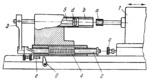
Description
In the grinding process, grinding wheel a, mounted on wheelhead slide 1, enters the hole being ground in workpiece b. Rod 2, carrying cross-piece 3 on its left end, runs with its right end up against the face of screw c in slide 1. Upon travel of slide 1 to the right, grinding wheel a is withdrawn from the hole in workpiece b. At this, rod 2, whose end is no longer held by screw c, also moves to the right from the action of spring 4. As a result, plug gauge d, mounted on rod 5 which is secured in cross-piece 3, tries to enter the hole being ground in workpiece b. If the hole is undersize, the gauge cannot enter and stop screw e will not reach lever 6. When the smaller diameter of the two-step gauge enters the hole of workpiece b, stop screw e reaches and changes the position of lever 6. This changes the rate of infeed, and finish grinding begins. When the required hole diameter is reached, the second step of gauge d enters the hole and stop screw e shifts lever 6 to the position in which grinding ceases and the grinder is switched off.
$526$SL,FD$
|


