 Click to enlarge Click to enlarge
|
Description
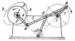
The lengths of the links comply with the conditions: A͞B=C͞B=M͞B=1; F͞C= 1.387; E͞A=0.557; D͞M=0.584; C͞E=1.324; F͞D=0.123; β=90°; Point M of connecting rod 3 in the four-bar linkage EABC describes symmetrical connecting-rod curve b-b. Link 4 is connected by turning pair M to connecting rod 3 and by turning pair D to link 2. Link 2 is designed as a flywheel rotating about fixed axis F. For the specified dimensions, one revolution of crank 1 corresponds to two revolutions of flywheel 2 in the same direction or to four revolutions in the opposite direction.
$601$LW,6L$
|


