 Click to enlarge Click to enlarge
|
Description
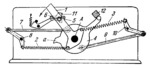
When handle 1, mounted freely on shaft A, is turned counterclockwise, springs 2 and 3 are stretched and actuate link 4 through links 7, 8, 9 and 10. But link 4 cannot overtake handle 1 because its lug a engages pawl 11 which is pivotted on handle 1 and is actuated by spring 5. When pawl 11 runs up against stop 6, it overcomes the resistance of spring 5 and turns, releasing lug a of link 4. Then link 4, actuated by springs 2 and 3 through levers 7, 8, 9 and 10, turns until its other lug reaches stop 12. When handle 1 is turned further, springs 2 and 3 are stretched again. Pawl 11, bearing against stop 6, engages lug a of link 4. When the lever is released, the stretched springs return the mechanism to its initial position. Thus, the torque on shaft A, transmitted from handle 1 to link 4, is determined by the rigidity of springs 2 and 3 and the arrangement of levers 7, 8, 9 and 10.
$811$LW,S$
|


