 Click to enlarge Click to enlarge
|
Description
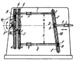
The lengths of the links comply with the condition: A͞͞B=A͞͞C=k. Cranks 4 and 5, turning about fixed axis A, are connected by turning pairs B and C to sliders 6 and 7 which move in guides d-d and e-e of links 1 and 2. Links 1 and 2 slide in fixed guides p and q. Link 1 is connected by turning pair E to slotted link 10. Link 2 is connected by turning pair F to slider 8 which moves along slot f-f of link 10. Link 3 slides in fixed guide 1 and is connected by turning pair D to slider 9 which moves along slot f-f of link 10. The displacement of link 3 equals s₃=m*sin(ϕ₁) ±n*sin(ϕ₂) where m=kb/(a+b)=constant, n=ka/(a+b)=constant, ϕ₁ and ϕ₂ = angles of rotation of links 4 and 5. Thus the linear displacement of link 3 is obtained as the sum or difference of the linear displacements of links 1 and 2.
$1259$LG,MO$
|


