 Click to enlarge Click to enlarge
|
Description
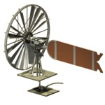
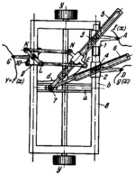
When styluses A and D, mounted on sliders 1 and 2, are moved along the corresponding curves f(x) and g(x), sliders 3 and 4 move along the slots of links 5 and 6. Sliders 3 and 4 are connected to sliders 1 and 2 by turning pairs. Slotted links 5 and 6 are connected by turning pairs to slider 7 which moves along guides a of carriage 8. Sliders 1 and 2 move along the right- and guide of carriage 8, parallel to they-axis. Along the left- hand guide, also parallel to the y-axis, moves integrating slider 9. The motion of slider 9 is control d by wheel 10 which rolls along the plane of the drawing. The plane of wheel 10 is maintained parallel to the axis of slotted link 5 by means of parallel-crank linkage KNEL whose side NE is perpendicular to link 5. Slotted link 6 slides along guide d of hyperbolic shape shown as a line and mounted on frame 8 so that the axis of slot a and the axis b of the right-hand guide of frame 8 are asymptotes of the hyperbola xy=1/4. The plane of wheel 10 makes the angle φ with the x-axis and tan(φ)=f(x)g(x). Stylus G of integrating slider 9 traces the curve F8x)=∫(f(x)g(x))dx.
$1314$LG,MO$
|


 GERMANY
 SPAIN
SPAIN ROMANIA
 FRANCE
 ITALY
ITALY