|
Description
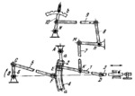
Connecting rod 1 is connected by turning pairs E and D to circular slider 2 and to rod 3 of the valve. Slider 2 moves along circular guides a-a of link 4 which turns about fixed axis A. Link 4 is oscillated by connecting rod 5 which is connected by turning pairs F and C to link 4 and to crank 6. Crank 6 rotates about fixed axis B. Link 7 is connected by turning pairs K and M to link 1 and to bent lever 8 which turns about fixed axis H. Lever 8 is connected by intermediate link 9 to lever 10 which turns about fixed axis N. The stroke of the valve is varied by setting lever 8 to the proper position and fixing it by means of lever 10 which has a tooth entering one of the slots of toothed quadrant b.
$1331$LG,VG$
|


 Click to enlarge