 Click to enlarge Click to enlarge
|
Description
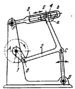
The lengths of the links comply with the conditions: A͞B=1, B͞C=3.1, C͞D=2.6, C͞E=3.0, A͞F=2.3, A͞D=4.5, F͞D=6.3 and B͞E=4.0. Point E of connecting rod 2 of the four-bar linkage ABCD describes connecting-rod curve a of which a certain portion approximates a straight line passing through point F. Slotted link 3 turns about fixed axis F and has slot b whose axis coincides with the straight portion of path a of point E. Slider 4 moves along slot b. When point B of crank 1 travels along the part of the circle indicated by a heavy continuous line, point E of connecting rod 2 moves along the portion of path a that approximates a straight line. During this period, slotted link 3 almost ceases to oscillate, i.e. it practically has a dwell.
$1339$LG,D$
|


