 Click to enlarge Click to enlarge
|
Description
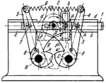
Crank 2 turns about fixed axis D and has roller a which moves along slot b of slider 1. Slider 1 reciprocates along guides c-c and has grooves d. Levers 4 and 5 turn about fixed axes C and B, and have rollers 3 and 7. When crank 2 turns clockwise, slider 1 pushes roller 3 to the right, turning lever 4 to its extreme position as shown. At this, spring 6 shifts lever 5 from the position shown to its extreme right-hand position (shown by dash lines). Levers 4 and 5 have cams 9 and 8 whose profiles are made up of circular arcs of equal radii. When slider 1 moves to the right, portion f of cam 8 slides along portion f' of cam 9, and in the extreme right-hand position of lever 5, portion g comes into contact with portion k', thereby locking the system. When slider 1 travels in the reverse direction it pushes roller 7 of lever 5, unlocking this lever. In the extreme left-hand position, portion f comes into contact with portion k, after which the cycle is repeated.
$1377$LG,SE$
|


