 Click to enlarge Click to enlarge
|
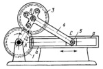
Description
Gear 1 rotates about fixed axis A and meshes with gear 3 which is rigidly attached to connecting rod 4. Crank 2 rotates about axis A and is connected by turning pair B to connecting rod 4 which, in turn, is connected by turning pair C to slider 5. Slider 5 moves along fixed guides a-a. When driving gear 1 rotates, slider 5 reciprocates. The transmission ratio between gear 1 and crank 2, i₁₂=ω₁/ω₂, where ω₁ and ω₂ are the angular velocities of gear 1 and crank 2, is equal to i₁₂=i₄₂i₁₄+(1-i₁₄) where i₄₂=ω₄/ω₂, i₁₄=ω₁/ω₄=-z₃/z₁, ω₄ is the angular velocity of connecting rod 4 and rigidly attached gear 3, and z₁ and z₃ are the numbers of teeth of gears 1 and 3. Transmission ratio i₄₂ is determined from the given dimensions of slider-crank linkage ABC. In one cycle of the mechanism, the speeds (rpm) of crank 2 and gear 1 are related by the condition n₁=n₂(z₁+z₃)/(z₁).
$2410$LrG,4L$
|


