 Click to enlarge Click to enlarge
|
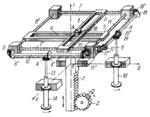
Description
The mechanism is intended for determining vector O͞A from its components (OA)x, (OA)y and (OA)z on the Ox, Oy and Oz axes. Projection (OA)x is entered into the mechanism by shaft 14 through intermediate shaft 13, and bevel gear 4 (keyed on shaft 13) which meshes with identical bevel gear 4'. Gear 4' is keyed on shaft 12 as are bevel gears 6' and 15' which mesh with bevel gears 6 and 15 keyed on lead screws 11' and 11. Lead screws 11' and 11 are connected by screw pairs to slide 5. When shaft 14 is turned, slide 5 travels parallel to axis Ox, thereby setting up projection (OA)x. In a similar way, when shaft 10 is turned, motion is transmitted through intermediate shafts 9 and 8, bevel gears 19, 19', 17, 17', 18 and 18' and lead screws 7' and 7 to slide 1 which thereby travels parallel to axis Oy. Slider 16 moves along slots a and b of slides 5 and 1. Projection (OA)z is set up by turning pinion 2 which meshes with gear rack 3. Rack 3 carries the whole system of links that sets up projections (OA)x and (OA)y. To enable bevel gears 4 and 19 to travel along axis Oz, shafts 13 and 9 telescope inside hollow shafts 14 and 10. The resultant vector is determined from the length and direction of line OA, where A is a point specified on slider 16.
$2493$LrG,MO$
|


