 Click to enlarge Click to enlarge
|
Description
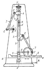
Crank 2 rotates about fixed axis B and is connected by turning pair C to connecting rod 3 which, in turn, is connected by turning pair D to slider 4. Slider 4 moves on shaft b along axis y-y. Shaft b has pin a which slides along slot d of tube 5. Tube 5 is connected by turning pair E to connecting rod 6 which, in turn, is connected by turning pair F to gear 7. Gear 7 rotates about axis K and meshes with gear rack 9. The lengths of the links comply with the conditions: B͞C=K͞F and C͞D=F͞E. Besides, in the initial position of the mechanism, crank 2 and gear 7 are positioned as shown. When crank 2 is turned, gear 7 turns through an equal angle and rack 9 is displaced along axis x-x, thereby setting up the magnitude of vector O͞A. When gear 1 is turned, shaft b turns and its pin a turns tube 5, together with link 6, gear 7, link 8 and rack 9, about axis y-y, thereby setting up the direction of vector O͞A.
$2494$LrG,MO$
|


