 Click to enlarge Click to enlarge
|
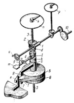
Description
One of the addends is entered by turning handwheel a. This rotates worm 1 which transmits rotation to wormwheel 2 mounted freely on shaft 3. Rigidly attached to wormwheel 2 is clutch member d. The mating clutch member b, freely mounted on shaft 3, engages clutch member c which is keyed on shaft 3. Thus, rotation of wormwheel 2 is transmitted by the clutch members to shaft 3 which carries hand k. Hand k indicates the magnitude of the addend on dial scale n. When pedal m is depressed, fork end l of zeroing device 4, turning about fixed axis o, disengages clutch members b and c. At this, shaft 3 with hand k is returned to its initial position (zeroed) by the action of a spring arranged between disks 5 and 6, and by lugs f and e. Disks 5 and 6 turn freely on shaft 3 and are connected together by a spring which tends to turn the disks with respect to each other. Lugs f and e of disks 5 and 6 bear against fixed stop 7 and limit rotation of the disks. L-shaped lever 8 is rigidly attached to shaft 3 and its end is also between lugs f and e of disks 5 and 6. By means of spring 9 fork end l holds clutch members b and c in engagement, enabling rotation to be transmitted from handwheel a to hand k. When shaft 3 is turned through a certain angle by rotating handwheel a, lever 8 overcomes the resistance of the spring between disks 5 and 6, and turns either disk 5 or 6, depending upon the direction of rotation of handwheel a. Then disk 5 or 6, as the case may be, tends to return shaft 3 to its initial position. Unintentional rotation of shaft 3 with lever 8 beyond the limits of stop 7 is prevented by lug f or e of disk 5 or 6, and by the worm gearing. The position of lever 8 opposite stop 7 corresponds to the zero position of hand k on dial scale n. The second, third and subsequent addends are entered in a similar way. Before entering each addend hand k is zeroed. Thus, the shaft of worm 1 is rotated through an angle which is the algebraic sum of the angles entered in by turning handweel a, and proportional to the sum of the addends. This sum is read off on dial scale p. By means of gearing 10, this sum can be directly entered into the required mechanism.
$2504$LrG,MO$
|


