 Click to enlarge Click to enlarge
|
Description
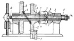
At normal permissible load, torque is transmitted from gear 1 to gear 2, which can rotate freely and slide along hollow shaft A, and then further through bar 5 to gear 6. Balls at the ends of bar 5 engage corresponding ball sockets in gears 2 and 6. Plunger 3 slides in hollow shaft A and is held in the position shown at normal torque by coil spring 4. Groove b of plunger 3 is engaged by fingers 7 which have rollers a at their other end resting on tapered hub d of gear 2. In case of overload, the pressure against the ball ends of bar 5 increases so that the bar pushes gear 2 to the right. At this, tapered hub d spreads fingers 7 forcing plunger 3 to the left and compressing spring 4. Plunger 3 depresses button 8 to stop the machine. When the excessive load is relieved, spring 4 returns the mechanism to the initial position.
$2539$LrG,C$
|


