 Click to enlarge Click to enlarge
|
Description
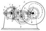
Crank 1 rotates about fixed axis A and is connected by turning pair E to slider 8 which moves along slot a of slotted link 7. Link 7 slides in fixed guides b-b. Gear 4 is rigidly attached to crank 1 and meshes with gear 5 which rotates about fixed axis B. Gear 5 meshes with gear 6 which rotates about fixed axis C and is rigidly attached to disk 2. Disk 2 is the workpiece in which the cam slot is to be machined. Machining is accomplished with end milling cutter 3 which rotates about axis D of link 7. In the version shown, a cam slot of a shape based on a sine law is machined. Gears 4, 5 and 6 have the same pitch radius.
$2557$LrG,FD$
|


