 Click to enlarge Click to enlarge
|
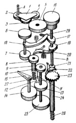
Description
Input shaft A transmits rotation to gear 5 through unidirectional device 1 always in the same direction (when gear 2 rotates counterclockwise, gear 3 meshes with gear 5, and when gear 2 rotates clockwise gear 4 meshes with gear 5). Gear 5 simultaneously drives gear 16 of the clockwork and gear 6 of the transmission mechanism. While gear 5 rotates, the clockwork spring is being continuously wound up. The clockwork is adjusted so that camshaft B, together with its mounted cams 17, 19 and 21, makes one revolution per second. During the first half of this period, lever 18 is turned by cam 17 to a position in which gears 7 and 8 are in engagement, and pawl 20, actuated by cam 19, is withdrawn from gear 8. Motion is transmitted to hand 15 through gears 7, 8, 9 and 10, pins 11 and 12, and gears 13 and 14 (gear 13 rotates freely on its shaft). Hand 15 turns through an angle proportional to the angle of rotation in one-half second of the shaft being tested. Springs 26 and 27 are wound up. During the second half of the period, lever 18 is turned by compressed spring 28 so that it retracts the shaft of gears 6 and 7, disengaging gear 7 from gear 8. During this interval of time, hand 15 with gears 14, 13, 25 and 24 and ratchet wheel 23 remain stationary since double-ended pawl 22 engages the teeth of ratchet wheel 23, preventing its rotation. Gears 8, 9 and 10 with pin 11 are retracted by spring 27 to their initial position. If the angular velocity of the shaft being tested remains unchanged during the next and subsequent periods of operation of the tachometer, then pin 11 of gear 10 approaches pin 12 of gear 13, and hand 15 is stationary. If the speed of the tested shaft is reduced, then pin 11 does not reach pin 12, and when pawl 22 is retracted from ratchet wheel 23 (pawl 20 engages the teeth of gear 8 during this interval), hand 15 is turned in the opposite direction by spring 26 until pin 12 runs up against pin 11 of gear 10 (stationary at this time). If the speed of the tested shaft is increased, then pin 11 of gear 10 runs up against pin 12 of gear 13 and turns the pin together with gears 13 and 14 and hand 15, so that the hand is deviated through a larger angle. Spring 26 is additionally wound by this motion. Thus each new value of the angular velocity of the shaft being tested is indicated by hand 15.
$2802$CmG,M$
|


