 Click to enlarge Click to enlarge
|
Description
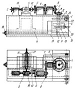
Shaft 22 rotates about fixed axis A and is driven by worm 1 which rotates about fixed axis B and worm wheel 2 which rotates about axis A. Keyed to shaft 22 are disk 4 with guides and bevel gear 3. Slide block 19 can be adjusted along the guides of disk 4 and locked in the required position by screw 20. Slide block 19 carries the bearing of pin 11 whose projecting part is of semicircular shape. When shaft 22 rotates, pin 11, whose flat surface engages plate 12, which is secured to the base, displaces slides 14 and 21, mounted on carriage 13. At the same time, cam blank 5 is rotated about fixed axis C-C through bevel gears 3 and 6, spur gears 7 and 8, and links 9 and 10. The slot is machined in blank 5 by end milling cutter 16 and the required axial travel of the blank is set up by means of screw 20. The minimum distance from the end face of the blank to the cam slot is set up by adjusting slide 14 longitudinally with screw 18. The depth of the cam slot is set up by adjusting cross slide 15 with screw 17. The pitch of the cam slot is set up by installing the required change gears 3, 6, 7 and 8.
$2840$WG,FD$
|


