 Click to enlarge Click to enlarge
|
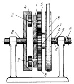
Description
Carrier 1 is keyed to shaft A and is connected by turning pairs to pairs of planet gears, consisting of gears 2 and 5, and gears 3 and 6, each pair being rigidly attached together. Internal gear 4 is keyed to shaft B and meshes with planet gears 2 and 3. The rotation of driving shaft A is transmitted through carrier 1 and gears 2 and 3 to driven shaft B, and through gears 5 and 6 to gear 7 which is freely mounted on shaft A. Gear 7 has lug a which engages either pin b or pin d, secured in shaft A, depending upon the direction of rotation of the shaft. When shaft A rotates in the direction shown by the arrow, lug a engages pin d and gear 7 rotates together with shaft A. At this, gears 2, 3, 5 and 6 rotate gear 4 and shaft B at an angular velocity equal to that of shaft A. If shaft A is reversed, gear 7 is braked by belt 8 and lug a begins to move from pin d to pin b, and gear 7 lags behind shaft A and carrier 1. At this, gears 2, 3, 5 and 6 begin to rotate and drive gear 4 and shaft B which rotates in the same direction as shaft A. The sizes of the gears are such that shaft B rotates at a higher angular velocity than shaft A. As a result, shaft B overtakes shaft A, eliminating the backlash of a special amplifier (not shown). When lug a reaches pin b, gear 7 rotates together with shaft A and the speed of shaft B is equal to that of shaft A. The distance between pins d and b is adjusted to exactly compensate for the backlash of the amplifier.
$2935$CxG,ML$
|


