 Click to enlarge Click to enlarge
|
Description
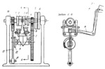
Pulley 5 is driven from an electric motor and is keyed, together with gear 4 and clutch member 17, to a sleeve mounted freely on shaft 3. From gear 4 rotation is transmitted to gear 7 which is keyed to a shaft together with cylindrical cams 10 and 11 and crank disk 12. The pin of disk 12 engages the slot of slotted lever 13, oscillating it about pin 19. The upper end of lever 13 has a gear segment which meshes with pinion 18, rotating the pinion alternately in each direction. Pinion 18 and clutch member 1 are keyed to a sleeve which is mounted freely on shaft 3. Pulley 6 is keyed to shaft 3 and clutch member 2 slides along shaft 3 on a feather. Clutch 2 is shifted into engagement with either clutch member 1 or 17 by shifting yoke 9. When clutch members 1 and 2 are engaged, pulley 6 rotates alternately in each direction; when clutch members 2 and 17 are engaged, pulley 6 rotates in the same direction as pulley 5. Shifting yoke 9 is shifted to the right or left by cylinder cam 10 or 11 when the cam engages one of the pins 8. Either pin 8 is pushed downward, and into contact with a cam, by bell-crank levers 14 and 15 (see Section A-A) which are actuated by cams 16 mounted on a camshaft (not shown).
$2936$CxG,ML$
|


