 Click to enlarge Click to enlarge
|
Description
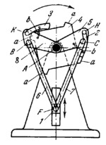
Links 5 and 8 and four-tooth ratchet wheel 4 turn independently of each other about fixed axis A. Connecting rods 7 and 6, of equal length, are connected by turning pairs C and B to links 5 and 8, and by turning pairs F to slider 1 which moves along fixed guides. Links 5 and 8 are connected by turning pairs H and K to pawls 2 and 3 which engage teeth a of ratchet wheel 4. Springs b hold pawls 2 and 3 against wheel 4. When slider 1 travels downward, pawl 2 turns ratchet wheel 4 clockwise through 45°; when slider 1 travels upward, pawl 3 turns wheel 4 through another 45° in the same direction. Then the cycle is repeated.
$1826$LR,ML$
|


