 Ansicht vergrößern Ansicht vergrößern
|
Beschreibung
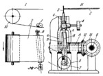
When belt 2 starts to slip off its pulleys, for example, in the direction shown by the arrow, guide roller 1 turns about fixed axis B (see Fig. I). The friction force between belt 2 and roller 1 returns the belt to its central position. The roller is turned by the mechanism shown in Fig. II. Weight 4 holds link 3 in constant contact with the edge of belt 2. Pulley 5, powered from an independent drive, reciprocates slider 6 through crank 7 and connecting rod 8. Slider 6 is connected by a turning pair to link 3. When belt 2 is in its proper position, link 3 is in the position shown in Fig. II and pawls a, rigidly attached to link 3, idle. When belt 2 begins to slip off in either direction, link 3 is deviated with the pawls. At this one of the pawls transmits intermittent rotation in the required direction to ratchet wheel 11 which is keyed on shaft A together with bevel gear 12. This gear meshes with bevel gear 13 which turns screw 9. By means of a nut (shown schematically with the screw in Fig. I) screw 9 turns roller 1 in the required direction about axis B.
$1848$LR,FD$
|


