 Click to enlarge Click to enlarge
|
Description
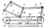
Link 1, designed as a bent lever, is connected by turning pairs A and B to pulleys 7 and 3, of equal diameter, and by turning pair F to link 2 which is designed as a bent lever. Flexible link 8 runs over the pulleys and is rigidly secured at points H and K to the base. Links 4 and 5 are connected by turning pairs G to flexible link 8 and by turning pairs E and C to links 2 and 6. Links 6 and 2 are connected together by turning pair D. When link 1 has straight translational motion, links 2, 4, 5 and 6 have complex motions.
$1950$FL,Cr$
|


