


|
|
|||||||
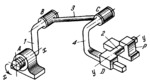
LEVER-SCREW SPATIAL MECHANISM |
|||||||
|---|---|---|---|---|---|---|---|
 Click to enlarge Click to enlarge
|
Description
Link 1 is connected by screw pair A to the fixed link and by turning pair B to link 3 which, in turn, is connected by turning pair C to link 4. Link 4 is connected by sliding pair D to link 2 which slides in fixed guide p. Screw motion of link 1 about and along axis x-x is converted into sliding motion of link 2 along axis y-y which is parallel to axis x-x. The axes of pairs B and C are also parallel to axes x-x and y-y. |
||||||
| Linked items | |||||||
|
|||||||
| Permanent links | |||||||
|
|
|||||||
| Data provider | |||||||
|
|
|||||||