 Click to enlarge Click to enlarge
|
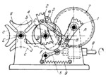
Description
The lengths of the links comply with the conditions: A͞B=D͞C and B͞C=A͞D. Link 1 is rigidly attached to worm wheel 7 which rotates about fixed axis A. Link 1 is a crank of crossed- crank linkage ABCD. Crank 2 of this linkage rotates about fixed axis D and is rigidly attached to pin wheel 3 and cam 4. Geneva wheel 6 rotates about fixed axis E and lever 5 turns about fixed axis F. Pin wheel 3 has pin a and Geneva wheel 6 has slots b. During dwell of Geneva wheel 6 the concentric surface of pin wheel 3 engages a concave surface c of the Geneva wheel to lock the latter. Worm wheel 7 is driven by worm 8. Rotation is transmitted from worm wheel 7 to pin wheel 3 and cam 4. To prevent reverse rotation of link 2 at the extreme (dead-centre) positions, the ends of links 1 and 2 have teeth which periodically mesh with each other. Pin wheel 3 transmits rotation to Geneva wheel 6, and cam 4 oscillates lever 5. Spring 9 holds lever 5 in contact with cam 4.
$1752$GL,D$
|


