 Click to enlarge Click to enlarge
|
Description
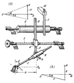
Link 2 turns about fixed axis C. Link 3 has pin a which is connected by a turning pair to slider 9 moving along the axis of link 2. Link 3 is connected by a sliding pair to link 4 which is designed as a nut moving along screw 5. Link 3 has gear rack 8 which meshes with long gear 6. Gear 6 also meshes with gear rack 7 which slides in fixed guide 10. The mechanism converts the system of coordinates shown in Fig. a to the one shown in Fig. b. The conversion of a system with the coordinates α, ξ and H into a system with α, r and z is carried out according to the transformation formulas z=H and r=H cot(ξ). Angle ξ is entered by turning link 2. Height H is entered by turning screw 5. The vertical displacement of rack 8 is B₀B=H cot(ξ). Rack 8 drives gear 6 which, in turn, displaces rack 7 whose displacement equals B₀B=H cot(ξ)=r.
$1762$GL,MO$
|


