 Click to enlarge Click to enlarge
|
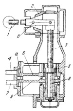
Description
When lever 1 is turned in a horizontal plane it turns housing 2 and shaft 3. Gear 5 is rigidly mounted on shaft 3 and fits in the internal gear of link 6, the two gears being the members of a toothed coupling. The left-hand end of link 6 is a gear segment which meshes with gear rack a of slider 4. Thus rotation of shaft 3 is transmitted through gear (coupling member) 5 and link 6 to shift slider 4. When lever 1 is turned in a vertical plane it shifts shaft 3 vertically. This motion is converted by helical gear 8, fitting into the internal helical gear of link 9, into rotation of link 9. Through the gear segment at the left- hand end of link 9 and a gear rack, displacement of shaft 3 is transmitted to shift slider 7. In this way, when lever 1 is shifted horizontally or vertically, it shifts either slider 4 or slider 7 which changes the speeds in the feed gearbox (not shown).
$1774$GL,SE$
|


