 Click to enlarge Click to enlarge
|
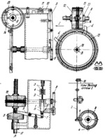
Description
When shaft 17 rotates counterclockwise about fixed axis A, slide 1 reciprocates and plunger 2 feeds separate chain links 3 from magazine 4. This motion is derived from face cam 5 and levers 6 and 7. The feeding of the definite number of chain links required is obtained by adjusting dogs a on disk 8. When disk 8 rotates, lever 9 is turned and latch 10 periodically locks slide 1 by acting on member 11. When switching cam 12, keyed to shaft 17, rotates, it rotates gear 13 counterclockwise about fixed axis B. At this, right-hand dog d engages rack 14, shifting it to the left. This turns pinion 15 clockwise, switching the thread ridges to the position shown by dash lines. By the action of a spring, bolt 16 locks gear 15 in this position. After this, gear 13 begins to rotate clockwise and continues until left-hand dog d switches the thread ridges back to their former position. Thus disk 8, keyed to shaft 18 together with gear 13, is turned periodically through the required angle. This angle is varied by adjusting dogs d on gear 13.
$3177$CmL,ML$
|


