 Click to enlarge Click to enlarge
|
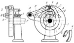
Description
When face cam 1 rotates clockwise about fixed axis F, roller a of follower 2 passes a long portion b of the cam groove, running up against latch 3 and turning it to the right. Latch 3 is rigidly attached to link 5 of a parallel-crank linkage consisting of links 5, 6 and 7. Axes B and C of links 5 and 6 are in cam 1. Latch 4 is rigidly attached to link 6. When latch 3 is turned counterclockwise by roller a, latch 4 turns in the same direction, permitting roller a to enter the upper portion of concentric groove c. As cam 1 continues to rotate, roller a again turns latch 3, returning it clockwise to the position shown, so that in the next revolution of cam 1, roller a passes from concentric groove c to portion b. While roller a is in portion b, follower 2 has an oscillating motion about fixed axis A. To two r evolutions of cam 1, follower 2 swings once in each direction. Unintentional motion of latches 3 and 4 due to gravity is excluded because link 7 consists of two strips, one on each side of links 5 and 6. Springs 8 hold the strips against links 5 and 6, creating a friction drag that prevents unintentional motion of the latches.
$3182$CmL,ML$
|


