 Click to enlarge Click to enlarge
|
Description
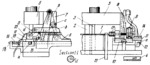
Strip stock 1 is fed to the right so that its end enters recess d in shaft 17. Then punch-holder 5 descends and the stock is pierced by punch 2 and cut off by punch 3, finished part 4 remaining in recess d. As the press ram and punch-holder 5 ascend, cam slot b of cam plate 7, mounted on punch-holder 5, acts on roller c of lever 8, moving slide 6 to the left. At this, shaft 17, to which link 9 is keyed, is turned 90° counterclockwise. When the inner edge of slide 6 reaches the inner end of slide 10, the latter begins to move to the left, compressing spring 16. In this motion, part 4 is placed over rod 13. As slide 10 continues moving to the left, roller a of cross-slide 11 engages fixed cam 12, pulling the cross-slide to the right (in the right-hand view) together with shaft 17 which is thus removed from part 4, allowing it to drop to the bottom of rod 13. As the ram and punch-holder 5 descend again, cross-slide 11 is returned to its initial position by spring 14 and is locked to slide 10 by spring-actuated latch 15. Slide 6 is returned to its initial position by the action of cam slot b on roller c of lever 8. Slide 10 is returned to its initial position by spring 16 so that the flange of stud 18 contacts the fixed base. Continued motion of slide 6 turns shaft 17, through link 9, back to its initial position, ready to receive the next part.
$3243$CmL,SF$
|


