 Click pentru a mări Click pentru a mări
|
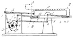
Description
Rigidly attached plate cams 1 and 2 rotate about fixed axis A. Follower 5 oscillates about fixed axis B and carries roller 3 which rolls along the working surface of cam 1. Follower 11 oscillates about fixed axis E and carries roller 4 which rolls along the working surface of cam 2. Link 6 is connected by turning pairs C and D to follower 5 and to transfer member 7 with rack a. Link 10 is connected by turning pairs M and K to follower 11 and to bellcrank lever 9 which oscillates about fixed axis L. Links 11 and 9 are connected by turning pairs F and N to sliders 12 and 8 which move along guides e and b of member 7. The lengths of the links comply with the conditions: E͞F=L͞N, M͞E=K͞L and M͞K=E͞L. When cams 1 and 2 rotate, rack a has a translational motion along closed rectangular path q, remaining parallel to its initial position. This is achieved by proper design of cams 1 and 2.
$3246$CmL,SF$
|


