 Click to enlarge Click to enlarge
|
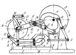
Description
Face cam 1 rotates about fixed axis A and has profiled groove a. Followers 2 and 9 oscillate about fixed axes B and G, and carry rollers 15 and 16 which roll and slide along groove a. Driven drum 11 rotates freely about fixed axis F. Shoe 13 turns freely about axis P of link 8 which is connected by turning pairs M and L to links 10 and 7. Link 10 oscillates about axis F and has straight slot b. Follower 9 has straight slot d. Bolt 14, used to adjust the mechanism, can be set in various positions along slots b and d, and clamped so that it slides along either slot 6 or slot d. Link 7 is connected by turning pair K to bell- crank lever 6 which oscillates about fixed axis R. Shoe 12 turns freely about axis T of bellcrank lever 5 which oscillates about fixed axis E. Levers 6 and 5 carry rollers 17 and 18 which roll and slide along cam slots c and e of sliding cam 4. Cam 4 reciprocates along fixed guides f-f and is driven by connecting rod 3 which is connected by turning pairs D and S to cam 4 and to follower 2. When cam 1 rotates continuously, drum 11 rotates intermittently with dwells. Rotation of the drum, corresponding to the feeding process of the material, is accomplished by shoe 13 during the periods when it is pressed against the surface of the drum and shoe 12 is withdrawn from the surface. Dwells of the drum occur when shoe 12 is pressed against its surface and shoe 13 is withdrawn.
$3253$CmL,SF$
|


