 Click to enlarge Click to enlarge
|
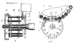
Description
Conveyer wheel 1 carries caps 2 into which cork disks 3 have been assembled automatically in a previous operation. The purpose of the inspection mechanism is to check whether all the caps contain cork disks and to remove caps which do not. Caps 2 are carried in recesses of ring b which is rigidly attached to wheel 1. Flanges 4 are rigidly attached together and to gear 7, and rotate about fixed axis A. Gear 7 meshes with ring gear 6 which is rigidly attached to wheel 1. Flanges 4 carry sliding plungers 5 and are rotated through gears 6 and 7 so that each plunger engages a cap. The plungers are held down by light springs 10. Lifters 8 at the top end of plungers 5 contact the working surfaces of fixed cams 9 and 11. Cam 9 pulls the plungers upward at position c, compressing springs 10, and releases them at position a so that each plunger drops into a cap. If the given cap 2 has a cork disk 3, the corresponding plunger 5 rests on the disk and its lifter 8 is high enough to engage cam 11 which lifts the plunger out of the cap. If the cap has no cork disk, plunger 5 rests on the bottom of the cap and its lifter 8 is too low to engage cam 11 under which it passes. Since, in this case, the plunger is not lifted by cam 11 out of the cap, the latter is pushed by the plunger off conveyer wheel 1. The distance between the centres of the plungers equals the distance between the centres of the caps in their recesses on wheel 1.
$3259$CmL,M$
|


