 Click to enlarge Click to enlarge
|
Description
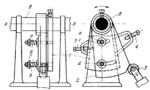
Plate 1 is rigidly clamped to shaft 8 and turns about fixed axis A-A. Cam 2 turns freely about axis A-A on the sleeve of plate 1 and is attached to the plate by studs a and b which pass through circular slots c and d in cam 2. Springs 6 and 7 produce friction between plate 1 and cam 2 so that they turn together. When shaft 8 turns counterclockwise, plunger 3 is depressed and closes a valve (not shown) as soon as cam 2 reaches screw stop 4. When shaft 8 turns clockwise, plunger 3 rises, opening the valve at the moment cam 2 reaches screw stop 5. Screw stops 4 and 5 control the time and amount of plunger motion. If the angle of oscillation of shaft 8 and plate 1 exceeds that set by stops 4 and 5, then, when cam 2 reaches either of the stops, plate 1 continues to turn, overcoming the friction drag between it and cam 2 due to springs 6 and 7.
$3263$CmL,PM$
|


