 Click to enlarge Click to enlarge
|
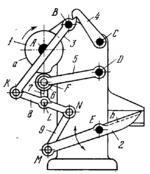
Description
Plate cam 1 rotates about fixed axis A. Follower 5 turns about fixed axis D and carries roller 6 which rolls along contour a of cam 1. Link 7 is connected by turning pairs F and L to follower 5 and link 8. Link 9 is connected by turning pairs N and M to links 8 and 2. Link 2 carries knife b and turns about fixed axis E. Link 8 is connected by turning pair K to link 3 which can turn about fixed axis B. Latch 4 turns about fixed axis C and can lock link 3. Link 2 with knife b oscillates only when link 3 is locked (as shown). If latch 4 is turned away to release link 3, cam 1 has idle rotation.
$3272$CmL,FD$
|


