 Click to enlarge Click to enlarge
|
Description
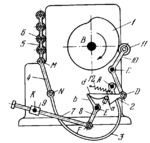
Plate cam 1 rotates about fixed axis B. Follower 10 turns about fixed axis C and carries roller 11 which rolls along the contour of cam 1. Follower 10 is connected by turning pair D to hook member 2 whose lug d slides along arm b of lever 8. Lever 8 turns about fixed axis E and is connected by turning pair F to link 7 which, in turn, is connected by a sliding pair to slider 9. Slider 9 turns about fixed axis K. From cam 1, keyed to the main shaft, motion is transmitted to hook member 2 which engages pin a of lever 3. Lever 3 oscillates about fixed axis A. By means of connecting link 4, connected by turning pairs N and M to lever 3 and to inking carriage 5, motion is transmitted to carriage 5 which carries inking rollers 6. To engage the inking motion, link 7 is pushed to the right so that it slides and turns in slider 9. This turns lever 8, allowing member 2 to engage pin a of lever 3. Carriage 5 with inking rollers 6 is pushed upward by the action of spring 12 on lever 3, and is pulled downward by cam 1. When link 7 is pulled to the left, arm b of lever 8 raises member 2 disengaging it from pin a of lever 3 so that inking carriage 5 stops in its upper position.
$3273$CmL,FD$
|


 GERMANY
 SPAIN
SPAIN ROMANIA
 FRANCE
 ITALY
ITALY