 Click to enlarge Click to enlarge
|
Description
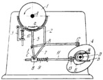
Rigidly attached plate cams 4 and 6 rotate about fixed axis D. Follower 2 oscillates about fixed axis B and carries roller 12 which rolls along the contour of cam 4. Link 11 carries roller 13 which rolls along the contour of cam 6. Fork b, rigidly attached to (or integral with) link 11, slides along roller 14 which rotates about axis D. Link 11 is connected by a sliding pair to slider 8. Triangular link 7 turns about axis B and is connected by turning pairs C and E to slider 8 and to brake shoe 5. During the working stroke, the impression cylinder turns about fixed axis A through an angle slightly larger than 360°. The impression cylinder is returned to its initial position as follows. Keyed to the shaft of the impression cylinder is disk 1 with cam dog a. Follower 2 pushes dog a together with the impression cylinder in the reverse direction. Link 3 serves to restrict the motion of dog a. The impression cylinder is stopped by brake shoe 5. Link 3 is held in position and roller 13 is held in contact with cam 6 by springs 10 and 9.
$3289$CmL,FD$
|


