


|
|
|||||||
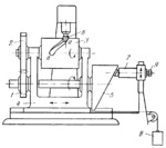
CAM-LEVER SPATIAL MECHANISM OF A TRACING ATTACHMENT FOR MILLING CYLINDER CAMS |
|||||||
|---|---|---|---|---|---|---|---|
 Click to enlarge Click to enlarge
|
Description
The spindle of milling cutter 6 runs in fixed bearings. Cam blank 3 and end cam 5 are rotated by a drive through meshing gears 1 and 2. Axial motion of cam blank 3 with slide 4 is obtained by profiled inverse end cam 5 which contacts fixed bar 7. Weight 8 holds cam 5 in contact with bar 7. Cam grooves a-a of various shapes can be milled by properly designing the working surface of cam 5 and by clamping bar 7 in various positions with bolt 9. |
||||||
| Linked items | |||||||
|
|||||||
| Permanent links | |||||||
|
|
|||||||
| Data provider | |||||||
|
|
|||||||