 Click to enlarge Click to enlarge
|
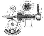
Description
Spindle 1, in housing 2, is driven about fixed axis A-A by gear 3 in which sleeve 4 and ball cage 5 are rigidly mounted. In the holes of cage 5 are guide bushings 6 with balls 7 which are acted on by springs 8. Mounted on plunger 9 is sleeve 13 which has an external semicircular groove. The plunger is shifted axially by lever 10 and operates a chuck (not shown) that clamps the workpiece. When plunger 9 is shifted to the right, the chuck opens and balls 7 enter the semicircular groove on sleeve 13, disengaging sleeve 4 and gear 3 which then rotates freely about spindle 1. Here the spindle is locked in a definite position by ball 11 of locking plunger 12. When plunger 9 is shifted to the left, the workpiece is clamped by the chuck, sleeve 13 is shifted to the left b y the spring, and ball s 7 are forced outward from the semicircular groove in sleeve 13 so that they engage recesses in sleeve 4. This engages gear 3 to spindle 1 which begins to rotate.
$3424$CF,ML$
|


