 Click to enlarge Click to enlarge
|
Description
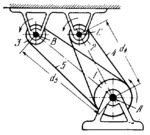
Pulley 1 rotates about fixed axis A. Two identical pulleys 2 and 3 rotate about fixed axes C and B. Flexible link 4 runs over pulleys 1 and 2; flexible link 5 runs over pulleys 1 and 3. The transmission ratios from pulley 1 to pulleys 2 and 3 are i₁₂= i₁₃= ω₁/ω₂=ω₁/ω₃=n₁/n₂=n₁/n₃=R₂/R₁=R₃/R₁ where ω₁, ω₂, ω₃, n₁, n₂ and n₃ are the angular velocities and speeds (in rpm) of pulleys 1, 2 and 3, and R₁, R₂ and R₃ are the radii of these pulleys. Under the condition that R₂=R₃<R₁, the lengths of flexible links 4 and 5 are L₄=π(R₁+R₂)+2(R₁-R₂)arcsin((R₁-R₂)/d₄)+2*sqrt(d₄²-(R₁-R₂)²) and L₅=π(R₁+R₃)+2(R₁-R₃)arcsin((R₁-R₃)/d₅)+2*sqrt(d₅²-(R₁-R₃)²) where d₄ and d₅ are the distances between axis A and axes C and B.
$3502$SFL,ML$
|


