 Click to enlarge Click to enlarge
|
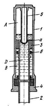
Description
Cylinder 1 is secured to the frame structure of the aircraft. Member 2 carries an aircraft wheel and has two bearings in cylinder 1: upper guiding sleeve 3 and lower bearing 4. Plunger 5 is rigidly secured to cylinder 1. Mounted on member 2 is reversing brake valve 6. Chamber A is filled with air under pressure. Chambers D and B are filled with a liquid. An annular clearance a for liquid flow is provided between member 2 and plunger 5. When the aircraft lands and the wheels strike the ground, member 2 travels upward. The air in the cylinder is compressed. Liquid is displaced from chamber D through annular clearance a into cylinder 1 and then through the holes in guiding sleeve 3, forcing away valve 6 up to its stop and, passing by this valve, filling chamber B. In the reverse stroke, member 2, owing to air pressure, travels downward and liquid from chamber B begins to flow into chamber A. At this, valve 6 is forced against upper guiding sleeve 3 and closes all of its holes for the down stroke, leaving only holes in the valve itself for liquid flow. From chamber A, the liquid flows into chamber D through annular clearance a.
$3640$SHP,DC$
|


