 Premi per ingrandire Premi per ingrandire
|
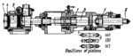
Description
When piston 1 is moved to the left by fluid entering the right end of its cylinder, sleeve 2, rigidly linked to the rod of piston 1, clamps piston rings (workpieces) 3 against locating ring 4 (in the extreme left-hand position of piston 1). When piston 5 is moved to the right by fluid entering the left end of its cylinder, clamping plate 7 and ring 4, linked to the rod of piston 5 by cross-piece 6 and two tie-rods 8, are pushed against sleeve 9 (in the extreme right-hand position of piston 5). At this time, when the pistons are in position a, the piston rings are machined. At the end of the machining operation, piston 1 with sleeve 2 moves to their extreme right-hand position and the newly loaded piston rings drop downward to the spindle axis. At this, piston 5 moves to its extreme left-hand position (see position b). Then piston 1 moves to the left to the end of its stroke, pushing the newly loaded rings to the working position in which they eject the machined rings (see position c). After this, piston 5 moves to the right, clamping the rings. New rings are put into the loading position during the machining operation.
$3746$SHP,GC$
|


