 Click to enlarge Click to enlarge
|
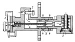
Description
The end of the turbine shaft is designed as valve spool 1 which fits into cylinder 2. Fluid admitted into cylinder 2 passes through holes in the valve spool to safety switch 3. The piston of the switch is subject to the action of spring 6 and the fluid pressure. Upon axial shift, valve spool 1 moves to the right and opens drain ports a. At this, the pressure of the fluid drops and spring 6 actuates the safety switch to stop the turbine. Spindle 4 and hand 5 serve to indicate axial shift of the turbine rotor. To check the position of the rotor, spindle 4 is pushed to the left until it contacts the central extension of the shaft. Then hand 5 indicates the axial position of the rotor on the scale.
$3765$SHP,Re$
|


