 Click to enlarge Click to enlarge
|
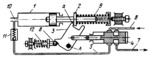
Description
When the pressure drops in the system, connected by pipeline 10 to the left end of cylinder 1, piston rod 2 is move to the left by spring 9 and its flange engages lug a of cam 3. This turns cam 3 about fixed axis A, shifting valve spool 4 to its left-hand position. At this, fluid is delivered by a pump through pipelines 6 and 5 and check valve 11 into the system. When the pressure in the system increases above a preset value, the piston and rod 2 are moved to the position shown and valve spool 4 connects the pump to the tank through pipelines 6 and 7. Pusher 8 and spring 12 flip cam 3 rapidly from one extreme position to the other.
$3897$LHP,Rg$
|


