 Click to enlarge Click to enlarge
|
Description
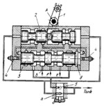
In the position shown, fluid under pressure, admitted into the directional valve through port f, is delivered to the power cylinder through port e. A part of the fluid is admitted into the housing of pilot valve spool 2 and from there, through one of the flow-control valves 4, to the right end of spool 3. Fluid from the exhaust end of the cylinder (through port b) is drained to the tank through valve 3 and flow-control valve 5 which regulates the speed of the machine tool table, linked to the piston of the power cylinder. The velocity of spool 3 and, consequently, the braking conditions are varied by adjusting flow-control valves 4. Flow-control valve 5 has a supplementary throttling slit a through which fluid from the ends of pilot spool 2 is drained to the tank. When lever 1 is turned about fixed axis A, pilot spool 2 is shifted to the right. At this, a part of the fluid under pressure is admitted to the left end of spool 3, shifting it to the right as well. During the first portion of its travel, until its end face blocks off fluid discharge from chamber 6, spool 3 moves at higher velocity. In its right-hand position, spool 3 delivers fluid to the other end of the power cylinder. The exhaust end of the cylinder is connected to the tank.
$3919$LHP,FC$
|


