 Click to enlarge Click to enlarge
|
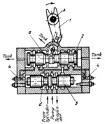
Description
In the position shown, fluid under pressure, admitted into the housing of directional valve spool 3, is delivered to the power cylinder. A part of the fluid is admitted into the housing of pilot valve 2 and from there, through one of the flow-control valves 4, to the right end of spool 3. Fluid from the exhaust end of the cylinder is drained through grooves of valve spools 3 and 2 to the tank. Braking of the machine tool table, linked to the piston of the power cylinder, is accomplished by cones a and d which throttle the fluid being drained to the tank. When lever 1 is turned about fixed axis A, pilot spool 2 is shifted to the right. At this, a part of the fluid under pressure is admitted to the left end of spool 3, shifting it to the right as well. In its right-hand position, spool 3 delivers fluid to the other end of the power cylinder. The exhaust end of the cylinder is connected to the tank.
$3920$LHP,FC$
|


