 Click to enlarge Click to enlarge
|
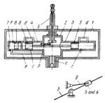
Description
Chamber 2, with two cylinders, 3 and 4, rotates in stationary housing 1. At one end, chamber 2 has shank a by means of which it is driven by the shaft whose speed is to be measured. Fitted into the other end of chamber 2 is stationary nipple b from which the pressure developed in the chamber is transmitted to a pressure gauge with a scale. Stationary nipple b has a pin connected by a turning pair to crank 9 which reciprocates the rod with pistons 5 and 6 when chamber 2 rotates (see kinematic diagram). Upon reciprocation of pistons 5 and 6, air drawn in through ports c is delivered through tubes d to chamber 2. From chamber 2 air passes through tube e to chamber 7 in which piston 8 slides freely. The pressure of the entering air tends to shift piston 8 to the right to open port f for releasing the air. On the other hand, centrifugal force tends to move piston 8 to the left to close port f. Consequently, the pressure established in chamber 7 and in chamber 2 is proportional to the centrifugal force of piston 8, i.e. to the square of the speed of shaft being tested.
$3935$LHP,M$
|


