 Click to enlarge Click to enlarge
|
Description
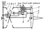
When lever 1 is turned clockwise about fixed axis A, lever 2, linked to lever 1 by flexible cables 3 and 4, turns in the opposite direction. Lever 2 turns about the same fixed axis B as elevator 5 and is hinged to the stem of valve spool 6. The valve is mounted on power cylinder 7 of the elevator drive. As lever 2 turns, it shifts spool 6 to the left so that fluid under pressure is delivered to the left end of power cylinder 7. Cylinder 7 is linked to lever 2 by pin a, fitting with some clearance in a slot of the lever. The rod of piston 8 is fixed. Cylinder 7 is moved to the left by the action of the fluid, turning the elevator. The ends of cylinder 7 are connected to the ends of cylinder 9, right end to left end and vice versa. The rod of piston 10 is hinged to lever 1. Thus, the effort required to turn lever 1 is proportional to the load on the elevator. The magnitude of this effort depends upon the ratio of cross-sectional areas of cylinders 7 and 9. Fluid from the exhaust ends of cylinders 7 and 9 drains through grooves of valve spool 6 back to the tank. When lever 1 is turned in the opposite direction, the elements of the mechanism operate in the reverse direction.
$3961$LHP,Co$
|


