 Click to enlarge Click to enlarge
|
Description
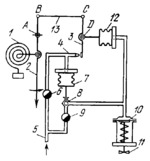
Hand 2, turning about fixed axis A, is linked to Bourdon tube 1 which is connected to the item whose pressure is to be regulated. Link 13 is connected by turning pairs B and C to hand 2 and to shutter 3 which turns about axis D, attached to bellows 12, and approaches nozzle 4. Compressed air is delivered through tube 5 and flow-control valve 6 to nozzle 4. The nozzle is also connected to bellows 7 to which the ball of valve 8 is linked. The air delivered to valve 8 throudgh flow-control valve 9 is at the same pressure as that delivered to nozzle 4. The chamber of valve 8 is connected to the atmosphere and to the membrane chamber of servomotor 10. When the pressure rises above normal, hand 2 turns counterclockwise, shutter 3 is retracted from nozzle 4, the pressure in bellows 7 drops, and the ball of valve 8 is raised, closing off air discharge to the atmosphere. After this, the pressure on the membrane of servomotor 10 increases and valve 11 is closed to some extent, reducing the supply of heat-carrying agent to the system. At the same time, the increased pressure stretches bellows 12, returning shutter 3 to its previous position. As a result, the ball of valve 8 is lowered and the pressure in servomotor 10 is stabilized. When the pressure in the system drops, the elements of the regulator operate in the reverse direction.
$4088$EHP,Rg$
|


