 Click to enlarge Click to enlarge
|
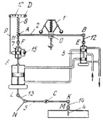
Description
Lever 2 is connected by turning pair O to the sleeve of governor 1. Links 11 and 12 are connected by turning pairs A, F, B and E to lever 2 and the piston rod of cataract 7 and to the stem of valve spool 3. Lever 5 turns about fixed axis C and is connected by turning pairs N and K to links 13 and 14. Link 13 is connected by turning pair L to the lower piston rod of servomotor 6, and link 14 is connected by turning pair M to shutter 4. When the speed of the item being regulated increases, the balls of centrifugal governor 1 move outward and its sleeve is raised, turning lever 2 about point A. This raises spool 3 of the valve, admitting fluid into the lower end of servomotor 6. The servomotor piston moves upward, lever 5 is turned about axis C and shutter 4 moves downward, reducing the supply of the heat-carrying agent to the system. As the piston of servomotor 6 moves upward, it raises the piston of cataract 7. At this, tie-rod 9 turns lever 10 clockwise about fixed axis D, raising the point of suspension of spring 8. This turns lever 2 about point O, shifting valve spool 3 downward. Fluid from the lower end of the cataract cylinder flows through flow-control valve 15 into the upper end. After this, spring 8 will no longer be stretched and point A will be located higher than its initial position. For this reason, valve spool 3 returns to its central position only at a speed exceeding the initial value.
$4095$EHP,Rg$
|


