 Click to enlarge Click to enlarge
|
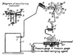
Description
The temperature in vessel 1 is regulated by varying the supply of heat-carrying agent flowing through regulating valve 3, which is linked to membrane-type servomotor 7. Compressed air is delivered to the system through tube e and is divided into two streams. The first passes through pressure reducer 4 into the space above bellows 5 and further to nozzle 6. The second stream passes through orifice a to the inner chamber of bellows 5, to the atmosphere through orifice b, and to the upper (membrane) chamber of servomotor 7. As shutter 8 is retracted from nozzle 6, the pressure acting on bellows 5 is reduced. At this, valve member 9 moves upward, closing inlet orifice a and opening discharge outlet b. This reduces the pressure on the servomotor membrane so that its spring closes valve 3 to some extent. When shutter 8 approaches nozzle 6, the bellows are compressed, valve member 9 moves downward, the pressure on the servomotor membrane is increased and valve 3 opens. The required temperature in vessel 1 is set by the monitoring indicator. Through tie-rod 12, handle 11 turns lever 13 about axis A, and monitoring hand 10, linked to lever 13, is set to the required temperature. At this, lever 14 turns about pin C of lever 15. Upon a change in temperature in vessel 1, hollow helical spring 16 of pressure-spring thermometer 2 either winds up or unwinds to some extent and, through tie-rod 17, lever 15 and pin C, turns lever 14 about axis B. This turns pen 18, rigidly attached to lever 15. Suspended from lever 14 is tie-rod 20 whose axis of rotation coincides with the geometric axis of rotation of pen 18 when the pen coincides with monitoring hand 10 (see the diagram of the monitoring indicator). In this position, tie-rod 20, through lever 19 and pin d, provides for light contact between shutter 8 and nozzle 6. Simultaneous motion of coinciding pen 18 and hand 10 has no effect on the position of shutter 8. When the temperature drops in vessel 1, helical spring 16 winds up somewhat and displaces pen 18 to the right of monitoring han 10. In turning, lever 14 lowers tie-rod 20 which turns lever 19 clockwise. At this, shutter 8 closes nozzle 6, pressure on the membrane of servomotor 7 is increased and valve 3 is opened, increasing the supply of heat-carrying agent to the system. The mechanism operates in a similar manner if monitoring hand 10 deviates from pen 18.
$4099$EHP,Rg$
|


