 Click to enlarge Click to enlarge
|
Description
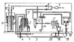
Link 19 turns about fixed axis A and is connected by turning pairs B and D to link 18 of the piston rod in servomotor 15, and to bellows 17. The concentrated solution is delivered through pipe 1 to mixer 2, to which water is also delivered through pipe 3. As a result of mixing, a solution of the required density is obtained and discharged through pipe 4. Compressed air is delivered to the system through pressure reducer 5 and flow-control valves 6 an 7. Air from flow-control valve 6 flows through pipe 8 whose end is immersed to a definite depth in vessel 9 which is filled with water. Water is delivered to the vessel through pipe 10 and drained through pipe 11. Air from flow-control valve 7 flows into mixer 2 through pipipe 12 whose end is immersed to a definite depth. Air from pipes 8 and 12 is released to the atmosphere, bubbling through the layers of liquid. Depending upon the density of the liquid, the resistance to the escape of air varies. In vessel 9 it is constant, while in mixer 2 it varies with the density of the solution. The difference in resistance to air escape establishes a pressure difference in pipes 8 and 12 which acts on membrane 13, linked to jet valve nozzle 14. A change in the density of the solution leads to a change in the pressure difference acting on membrane 13. As a result, nozzle 14 is diverted and, by means of servomotor 15, operates regulating valve 16 in the necessary direction. Valve 16 is linked to jet valve nozzle 14 through feedback device 21.
$4104$EHP,Rg$
|


